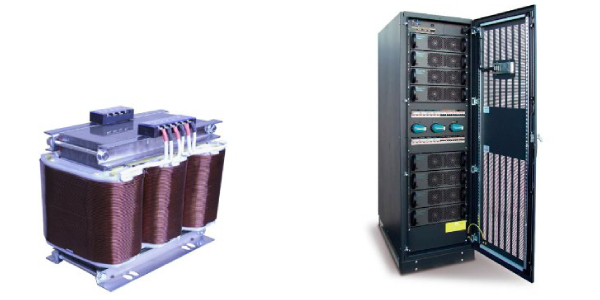
 First appearing at lower power levels, transformer-free UPS designs have been around two decades or so. A vast majority of designs below 30 kVA are now transformer-free, meaning that the UPS does not contain power line frequency magnetics (transformers or inductors). This transformer-free design trend is moving up in power levels because power line magnetics are both material and labor intensive. On the other hand, the high frequency power processing needed is technology intensive. In general, advances in technology mature sufficiently to support improved value to the customer without sacrificing needed reliability. Once that point is reached, the technology-intensive design becomes the preferred value leader. Technological advances in technology have had a similar impact upon switch mode power supplies as well as personal computers.
Transformer-free UPS: A growing trend
At higher power levels reaching above 30 kVA and now as high as 1100 kVA, the challenge is to switch high currents rapidly at high voltages without high losses or excessive peak voltages. Over the last decade, high power insulated gate bipolar transistors (IGBT) have matured enough to allow conversion frequencies of 10 kHz and above without large sacrifices in efficiency at these higher power levels. In addition, some creative control strategies permit further reduction of switching losses to the point where the new transformer-free technology UPS is competitive with the old technology UPS–even when measured in terms of system efficiency.
Transformer-free vs. legacy UPS designs
Figure 1 illustrates the basic topology of the legacy and new transformer-free technology UPS powertrain. A phase-controlled rectifier, while efficient and cost effective, produces large harmonic input currents and reduced input power factor which is unacceptable at many sites and incompatible with some generators. Large input inductors and harmonic filters are needed to bring the harmonics down to 5 to 10% total harmonic distortion (THD) and power factor (PF) up to >0.99 PF. These components add cost and weight and increase footprint. In addition, they do not hold THD down and PF up over a wide load range. They are typically effective only above 60% of full load. At light loads below approximately 40%, the input PF can actually become leading and will cause incompatibility with generators. The PF also varies with line voltage but is only specified at nominal line.
 THD and transformer-free UPS designs
In regards to harmonic distortion, the severity level depends upon the particular application and location. For example, a 10% distortion component at a low frequency causes far less voltage distortion than one at a high frequency. Without adequate input filtering, a rapid di/dt (current spike) resulting from SCR firing can cause severe line voltage notching and interfere with adjacent equipment. In fact, it takes more than 14% THD before the input PF is reduced below 0.990 by the THD alone.
Battery management advantages of a transformer-free UPS
Note that a half bridge converter can control battery voltage independent of bus voltage and also allows a range of battery voltages (e.g. 192 through 240 cells) to be accommodated. This converter also enables the battery to rest in an open circuit state to avoid continuous ripple current and the accelerated aging (especially at elevated temperatures) resulting from floating at a voltage significantly higher than open circuit voltage. With these additional capabilities, ABM® technology and other charging techniques can be more effective in extending battery service life. ABM technology is a feature of most Powerware® battery charger designs.
The IGBT rectifier stage supports the power drawn from the line while the Inverter stage supports the output current. With an input PF of >0.99, a load power up to 90% of rated kVA can be supported while maintaining ample reserve to recharge the battery. During periods of reduced line voltage, some recharge power is given up to ensure continued to support of output load. When the line level returns full/fast recharge capability will be restored.
With a SMALL Inductor/Capacitor (LC) low pass filter at the input, even the moderate di/dt changes in the input inductors are prevented from disturbing the line voltage – just as they are filtered at the output voltage by the same LC filter.
Read More: Powerware 9155 – 9355 (8-40 kVA)
Leave a Reply